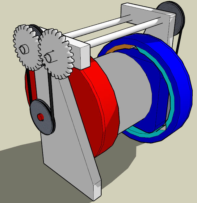
General view of the transfers of
coolant fluid for 2 PRATL machines
Conversion of the motion
The motion of the rotary annular
trilobic pistons
(PRA)
is a continuous rotation, but with alternates rotating axis. To convert
it into a continuous rotation with fixed axis, several solutions have
been developped by Pascal HA PHAM, inventor of the machines
(2,2F,2C) : rotative rod with 2 fingered rotules ; Oldham's
joint ; guidance by circular
triangular holes (LUM1, LUM2, LUM3) cut on a central rotor.
All these alternatives, as described in
the demands PCT 03.3921, and INPI 07.5990 and 07.6157 of Pascal HA
PHAM, are compatible with the device (1). So, as illustrated on figures
2B,2C,2D et 2F, the last
solution is kept with the following improvements, for cold (2F) or hot
(2C) PRATL machines :
- the trilobic piston (PRA,PRAF,PRAC) is
built with :
o one
trilobe (TRI,TRIF,TRIC)
o one
plate of tightness (PLA,PLAF,PLAC) bound of the trilobe
o at
least 3 braces (MAN1,MAN2,MAN3) bound of the plate
(PLA,PLAF,PLAC),
- the braces (MAN1,MAN2,MAN3) are always
to the
contact of the periphery of the holes (LUM1,LUM2,LUM3) cut in their
corresponding rotor
(ROT,ROTF,ROTC) , and,
- the rotors (ROT,ROTF,ROTC), actuated by
the braces,
turn around a fixed axis crossing the machines (2,2F,2C) exactly in
their
center.

To watch the...
Please wait a few minute for the download... to read in loop.
Others ways to convert the motion
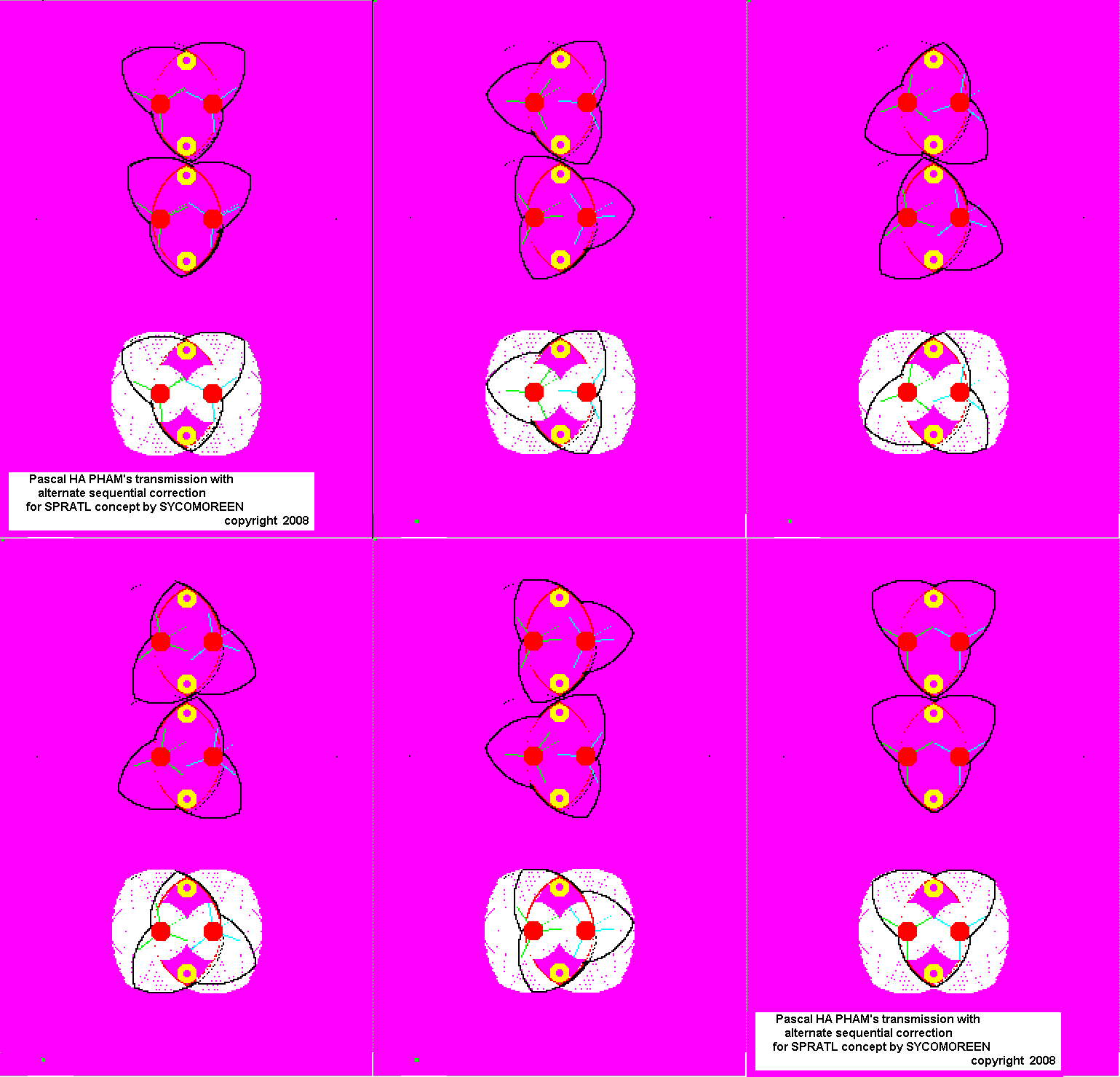
SYCOMOREEN is also working on the adaptation of a previous idea of Pascal HA PHAM to the SPRATL : the transmission to alternate sequential correction. It is based on two 3-teethed-wheels synchronized by a central gearing. You can see a preview on the pictures below:
While the motion is running, one wheel (for example : 2)
engages jointly with the trilobe and the other (2') is freed, but
synchronized with the engaged wheel trough the central gearing (1). A
cover (0) allow the rotations and the geometrical needs for the
gearings. Every 60° of rotation, the roles of 2 and 2' wheels are
permuted in a nearly instantaneous transition according to the homocinetic rotary motion they allows to obtain .
homocinétique qu'ils permettent d'obtenir.,
You can play with this motion by downloading this Excel file,
(right click, save as) programmed by Pascal HA PHAM. You should save it somewhere on your
computer (the direct execution may fail) and then to activate the
macros (this is not a virus...) and to push F2,F3,F4 and F5 keys as you want.
Recently JMB, alias Toto65, econologist forumer, has proposed an alternative with peripheral wheels which can be seen by pushing F1 key in the previous file, and here are some pictures of his design:


Precautions
of thermal insulation
In the simplest approach, as shown on
figure 2A, the
insulating muff (ISO) is absent and the rotors (ROTF) and (ROTC) are
mutually bound to make an only part (ROT).
Nevertheless :
- to block the thermal conduction and
radiance, an
insulating muff with sheets metal is placed, and can be more or less
sophisticated :
o achievement of vacuum around the
regenerator (RGN), or only in the concentric layers (ISO1,ISO2,ISO3)
inside the muff (ISO)
o internal reflecting faces of the layers
(ISO1,ISO2,ISO3) to send back the infra-red radiance emitted by the hot
zones of the
regenerator, and external black faces
to absorb the outside radiance.
- to avoid the direct heat transfer from
machine (2C)
to machine (2F), as illustrated on figures 2G and 2H, the rotor (ROT)
can be divided in 2 parts
(ROTF,ROTC), which are mated in an uniform velocity manner while
blocking the thermal conduction. The area of contact between (ROTF) and
(ROTC) is nearly zero. It is possible by using ponctual contacts
between (ROTF) and (ROTC).
Here, 3 ponctual contacts take place between the plane flutings (CAN)
cut in (ROTF), and 3 spheres (SPH) bound of
(ROTC). Moreover, (ROTF) will be optionnally reflecting and
(ROTC) dark.
Tightness of the rooms
The tightness is
different for the small rooms of the internal level (PC1,PC2,PC3) and
for the big rooms (GC1,GC2,GC3) of the external level of PRATL machines.
As drawn on figure 3L,
for the small rooms (PC1,PC2,PC3), 2 wide circular
surfacic contacts between the piston (PRA) and
the bi-arched core (NBA)
prevent the flights of fluid, except in the position of the
figure 3N, where the contact becomes lineic at the top of the
piston (PRA). However, this phenomenon is
extremely fleeting and thus negligible.
On the contrary, for the big rooms
(GC1,GC2,GC3),
there is only one surfacic contact between the piston (PRA) and the
cover (CAR), the other one having been replaced by a lineic contact
nearly permanent at the head of lobe: it is unfavorable for the
tightness. Thus, as described on figures 3K,3M and 3N, this lineic
contact becomes surfacic by small circular material
cut-off at the head of each lobe
(EMC1,EMC2,EMC3), and by 2 circular additions of material (AMC1,AMC2)
of same center and radius on the cover (CAR). Then, a vacuum in the
position of figure 3N
is obtured by one or several segments
(SEG1,SEG2,SEG3,SEG4) appreciably vertical and individually advanced
against the piston (PRA), either by a spring, either by a pressure of
fluid (not drawn).

These segments (SEG1,SEG2,SEG3,SEG4)
have a role of
tightness during a relatively short time of the motion (less than
10° of rotation angle for the trilobic
piston (PRA) around the position of the figure 3N) : all the rooms are
tightened nearly continously by surfacic contacts between the piston
(PRA), the core (NBA) and the cover (CAR). Another segments mounted on
the core or on the piston, as well as the dividing of the cover (CAR),
as described in the demand INPI 07.6157, are foreseeable too in order
to optimize the tightness.
Extension to rotary annular
polylobic pistons
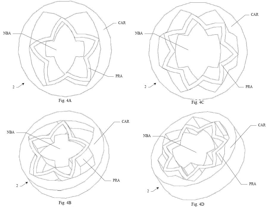
The device (1) can work with a polylobic
piston :
any odd number of lobes superior or equal to 3 is functionning. As
illustrated on the
figures 4A and 4B for a rotary annular pentalobic piston (PRA), and
4C and 4D for a rotary annular heptalobic piston (PRA), under
the
condition to modify the peripherical shapes of the cover
(CAR), of
the core (NBA) and of the holes (LUM1,LUM2,LUM3), the trilobic
machines (2,2F,2C) and their use with the device (1) in the setting of
Stirling's cycle, become widespread with odd
polylobic pistons, notably in term of
connections and conversions of motion.

For several reasons, the optimal
case remains
nevertheless the trilobic piston : loss of compactness, complexity of
the piston,
lessened tightness and non wanted compressions/relaxations of the fluid
during the cycle make that, the cases beyond the
heptalobic machine
will probably not find concrete applications and will stay merely
conceptual in the setting of Stirling's cycles.


