1.
General principles
The invention
appears in the helio-thermo-electric path, and more
especially in the thermodynamic solar energy.
The
thermoelectric power plants
have all chosen the way of the concentration of the solar radiance to
reach the high temperatures, necessary to have an effective
thermomechanical cycle of conversion of the collected solar energy.
However, these temperatures (about 600°C) are not sufficiently
high
to fulfill the high thermomechanical output known
in the thermal power stations (50% and until 60% in
combined
cycle) whose hot source is generally at more of 1000°C thanks
to
the use of very exothermic fuels (coal, oil, gas, nuclear
fission).
The present
invention prolongs the principle of the parabolic or
cylindro-parabolic mirrors.
However, in some cases, the
geometry of these mirrors is perfected, and the means of conversion of
the solar radiance in heat are distinctly different of the current art :
1. The place of focusing of
the radiance collected by the mirror constitutes the entry of an energy confining surrounding
wall (ECE)
whose particular geometry gives it some
anti-emissive properties.
2. The focused radiance
(4) engulfs itself in this cavity where it is progressively absorbed thanks to 2
different ways :
o
with multiple and partially absorbing reflections
and diffusions on the walls of the
cavity (7,9,10),
o
during its course between 2 successive impacts on the walls (7,9,10) of
the cavity when this one is filled by an
absorbing component


Focal
character of the miroirplacement of the ECE surrounding wall parabolic Shapes of
revolution focal distance & impact generated the focal plan
Vary focal distance from parabolic shapes of
revolution to parameter non hopeless r0
2.
The energy confining surrounding wall , key-of-arch of the
PHRSD
The surrounding
walls' anti emissive properties are gotten :
-
by the possibility to close completely the surrounding wall by a valve
(26) when the sun disappears,
- by
physico-chemical components,
set down on or between the walls, able
to absorb and to keep strongly the infrared radiance of a
black body at a few
thousands of Kelvin,
-
with
a geometry of the surrounding wall maintaining all luminous
rays inside the (ECE) with even hundreds of
absorbing reflections before they have their first opportunity to go
out of the energy confining room.
It is this last point that is crucial for the anti-emissive character
of the surrounding wall (ECE).
The best anti-emissive
geometries can be notably of three types :
TYPE 1: parabolic or
appreciably parabolic surfaces,
with disconcerted focusing points (of preference) and with preferably
aligned optic axes, one of long focal distance (9,9A,9B), the other of
short
focal distance (10,10A,10B) :
-
Concave / concave, or,
-
Concave / convex
defining an " afocal cavity
(6,6A,6B)"
Geometric, progressive and irretrievable trapping of the
parallel rays to the axis of the parabolas


Concave / concave afocal cavity


concave / convex afocal cavity
general situation of an ECE:
(12) insulations by the emptiness, mirrors (11) blocking infrared
radiance inside the cavity
")
3.
Conversion in heat
The
walls
(9,10,16A,16B) of the energy confining surrounding wall (ECE) imposes,
as
well to the captured rays that those re-emitted by the thermal
radiance, of very numerous absorbing reflections before having the
geometric
possibility to escape. Typically, these walls can be achieved in
steel or in heat-resistant materials.
Thanks to these hundreds
of partially absorbing reflections, it is possible to convert progressively the solar light into heat at
very high temperature (several thousands of
°Celsius).
A thermodynamic machine (32) can be mounted up to the contact of the
cavity
(6) in order to extract the heat for producing mechanical work with
the cold source constituted by the atmosphere or the outside soil,
according to a
thermodynamic motor cycle of Brayton-joule, steam, Stirling...
 The uses of the thus gotten heat are notably :
-
ecological ovens at
very high temperatures,
- chemical
and thermical thermolysis plants
-various thermodynamic
cycles to produce a mechanical work, then electricity via a generator.
As shown on the Fig. 13A, the
thermodynamic
machine (32) can be go up also on soil (20) under the condition to
bring him the heat collected in the energy confining surrounding wall
(ECE) by a
circulating fluid in very insulated hoses (27).
The device to convert heat into electricity will be advantageously a SPRATL engine.
The bottom of the opposite schema (13A) illustrates
the thermal storage in one
re-raising container whose thermal insulation uses the
principles already designed for the energy confining surrounding wall
(ECE).
With this approach, the storage can be important with a few
hundreds of kilograms of materials with strong thermal capacities:
water,
sand, stones, specific fluids...
It opens the
possibility to use at will
the energy storeed in diurnal period with a simple, efficient and
little expensive principle.
4.
Diagram summarizing the working of the energy confining surrounding
wall
 Illustration created
amiably and well stocked grâcieusement, by Toto65, forumeur
éconologiste
Illustration created
amiably and well stocked grâcieusement, by Toto65, forumeur
éconologiste5.
Patent and detailed documentation
Only in French at this time...
The demanding reader or wishing merely better to understand the
relevance of the PHRSD concept will be able to consult
- the scientific note
describing in detail the outputs of the PHRSD (fully in English !)with a
fine physical modelling of its energy exchanges.
- the PHRSD patent
without the claims,
- the nomenclature,
And the different families of faces:
- faces 1A to 1G and fig2
: relative to the parameters of impact of the
direct solar radiance on a mirror,
and to the generic conception of the
energy confining surrounding wall (ECE)
- faces 3A to 3B :
relative to the general arrangement of the mirror, its focal
properties and the integration of the ECE surrounding wall
- faces 4A to 4I
: relative to the parabolic
shapes of revolution and focal distance, and the impact
generated by the rays in the focal plan
- faces 5A to 5F
: relative to the parabolic possible extruded
focal shapes and the impact generated by the rays in the
focal plan
- faces 6A to 6I
: relative to the spherical shapes of revolution
and focal distance, and the impact generated by the rays in the focal
plan
- faces 7A to 7F
: relative to the spherical possible extruded
focal shapes and the impact generated by the rays in the
focal plan
- faces 8A to 8H
: relative to the different shapes to give to the entry of the energy
confining surrounding wall (ECE)
- faces 9A to 9D
: relative to the focusing of the different solutions of mirror
collector according to the mathematical
parameter r0
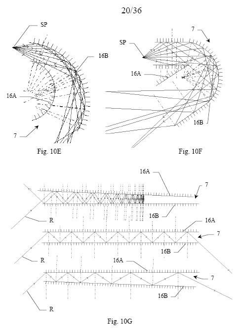
- faces 10A to 10G
: relative to the different shapes of anti-return passageways
favorable to the confinement of the rays collected
- faces 11A to 11Q
: relative to the different afocal anti-emissive
cavities combined to examples of anti-return
passageways
- faces 12A to 12D
; relative to the main elements of the hyperthermal trap of the direct
solar radiance
- faces 13A to 13B:
relative to variants of the trap, notably with
thermal storage of the energy and Stirling engine.
- faces 14A and 14B
: relative respectively to the variants "bi
anti-émissive high temperature oven"
(notably for thermolysis...)
and to the
hybrid variant
with solar photovoltaïc and solar concentration.
- faces 15A to 15D
: relative to the optimum arrangements
to constitute "efficient and ecological solar fields"
- The entire zip