The conversion of the
motion is probably a domain as important as its generation...
If one looks at the history of the volumetric motors,
which use pressurized gases rather than kinetic gases,
very few are the engines which
take care about
about this aspect. For
example, the engine with pistons, rods and crankshaft , possesses a
kinematics, that in
addition to be very unbalanced, immediately imposes a frozen law of
conversion : even while making vary the radius of the crankshaft or the
lentgh of
the rods, the kinematics of the TDC/BDC is deplorable (too much long
and
stationary). One could mention other examples, as the Wankel where the
evolution of the volume of the combustion rooms, according to the angle
of rotation
of the output shaft, is not controllable, because of an
epitrochoïdal geometry that imposes all as soon as the
triangular geometry of the rotor is chosen.
Most of the
engines
currently known aren't able to arbitrary impose
an evolution
of the volume of every room
according
to the angle of rotation of continually
rotating shaft of the motor.
And yet, at a time
where one tries
to
pilot the auto-ignition of gases by the rise of temperature during
the compression (with new field of research like the controlled
auto-ignition (CAI), high charge compression ignition (HCCI), active
thermo atmosphere (ATAC), and even piloted detonation...), very few
concepts worry about that and bring breaktough about the subject.
Only some inventors in Quebec noticed the advantage of a sudden and
intense TDC
to synchronize the auto-ignition of fresh gases very exactly with the
TDC, so that, in
a first time, the combustion is the most complete and clean, and in a
second time, the relaxation of gases occurs as early as possible to
push appropriately the mobile parts of their machine...
However it would be necessary to
be capable to generate the volume that one WANTS in EVERY ROOM
according to the angle
of rotation of the rotating shaft of the engine.
In the case of the SYCOMOREEN's rotary
pistons engines, it needs to
CONTROL the BEATINGS of the pistons... more precisely :
- their angular amplitude
- their minimal and
maximal angles of alternative rotation
- but also and especially the law of evolution of the beating
during a cycle "mini angle - > maxi angle - >
mini angle"
1.
Motion to convert
The typical PRBC engines are based on
p pairs of pistons distributed
linearly if
p = 1 and circularly as soon
as p
is
superior or equal to 2. The set of the centers
of rotation of every piston forms then :
-
if p = 1, a segment
-
if p superior
or equal to 2, a regular polygon with 2p sides
One defines then, with the help of an adequate cover, 2p
rooms
of variable volumes, which pass alternately from their minimal volume
to
their maximal volume, and it requires the intermittent contact between
every
piston and its 2 nearests neighbors. What
implies :
angular
amplitude of the motion of rotary pistons = Pi / p radian or 180 / p degrees
2.
Proposed system
It
is possible to use
a generic system of conversion of the rotative alternated motion of
every piston in a continuous rotation on a shaft of which the
axis of rotation is in the center of the said segment (if p=1), or of
the said regular
polygon (if p>=2), and that, whatever is p superior or
equal to 1, whose principle is the next
one :
From
eccentric pebbles in relation to the axis of rotation of the pistons
and bound of these pistons, one recovers 2p
motions of alternate translation along the mediators associated to the
rotation's centers of 2
consecutive pistons. This motion is
transmitted to 2p grooves, equipped themselves with
one or several
pebbles, which push on a continuously rotative central
cam, bound on the
output rotative shaft of the motor, or the power entry shaft of the
pump (or compressor).
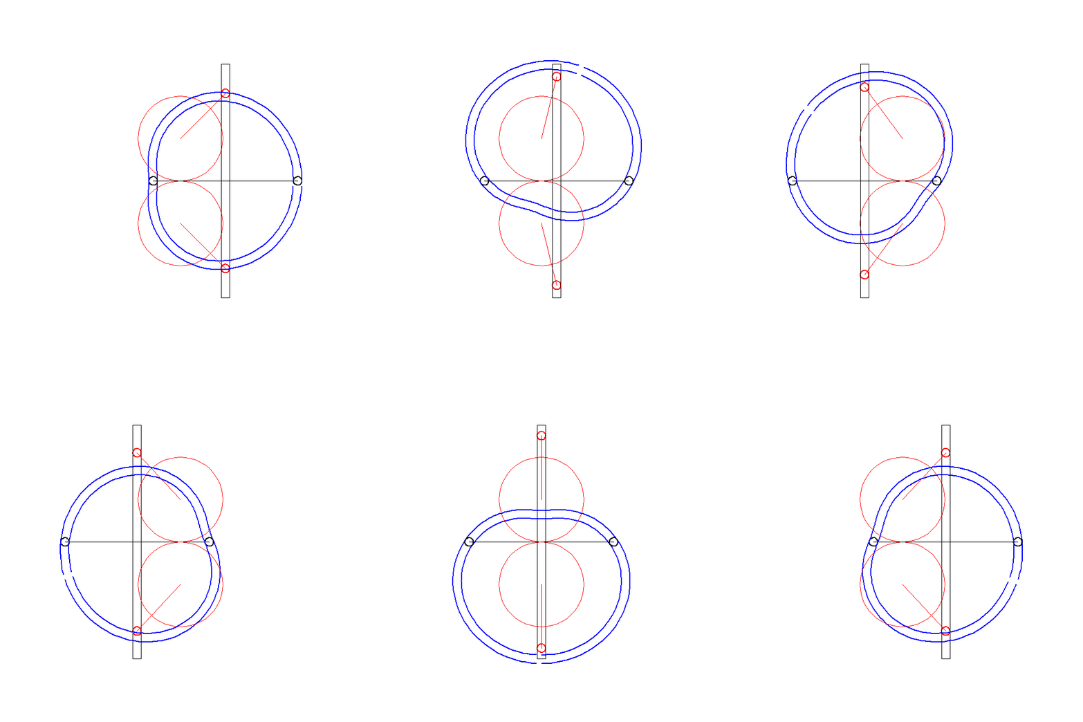
Generic system of conversion in
the case of only one pair of pistons.
glissière
: groove
came centrale : central
cam galet
excentré :
eccentric pebble
galet de glissière: groove's
pebble axe
des pistons rotatif :
piston's rotative axis
Every contact eccentric / groove pebble is systematically bilateral
either while making displace the eccentric pebble in a groove whose
width is worth the diameter of the pebble (what will be represented
here), either while bringing up a slippery sliding part in the groove
mounted rotative on the eccentric pebble.
2
options of cams are possible, and don't exclude themselves
mutually :
-
exterior
profiled cam when the pebble of groove is placed in
exterior radial position
- interior
profiled cam when the pebble of groove is placed in interior radial
position
- this
distinction becoming less clear for the particular case p=1
because the 2
symmetrical pebbles are in
contact with the same
profile of cam.
3.
Advantages of the mechanism
The
present mechanism based on a central rotative cam offers very numerous
assets :
- As regards to the transmission of
the efforts, pebble / cam or pebble / groove contacts are
very robust. And it's better when there are many pebbles, the power transits
trough
several symmetrical paths inside the machine, what
guarantees a better reliability and a lighter sizing of the parts..
- From p=2, the mechanism is perfectly and
intrinsically balanced because the effects of inertia of
the parts compensate themselves mutually. If p=1, the
mechanism, although functional, is not balanced :
- on
the one
hand because only one groove himself translate alternately
(traditionnal problem of pistons mounted on current engines),
- on
the other hand because the all the rotary pistons "throw themselves
together" in the same direction that the groove.
- The rotative central cam has a 2 Pi / p cyclic profile, it is therefore well balanced
in rotation and manages perfectly all other pairs of pistons because
they are also geometrically 2Pi / p cyclic.
- The
shape of the
cam reflects the kinematics chosen for the angular law of rotation
coupling the rotary pistons with the central rotative cam. The
shape of the cam can be computed with any law from the moment it
doesn't generate collisions between the pistons: one can
consider
some angular
beatings lower to Pi / p, with a any mini/maxi
angles(from the condition they don't generate collisions
between
pistons) and of the evolutions between the mini and maxi angles are
completely
free. For p=1, the symmetry of the
pebbles of the unique groove with the same cam for the 2 pebbles
remained valid provided that :
mini
angle = Pi - angle maxi
- The interior envelope of the cam
doesn't present a quick angle in order to assure a better
guidance.
- The
choice of an interior profiled cam encourages the compactness of the
engine.therefore
4.
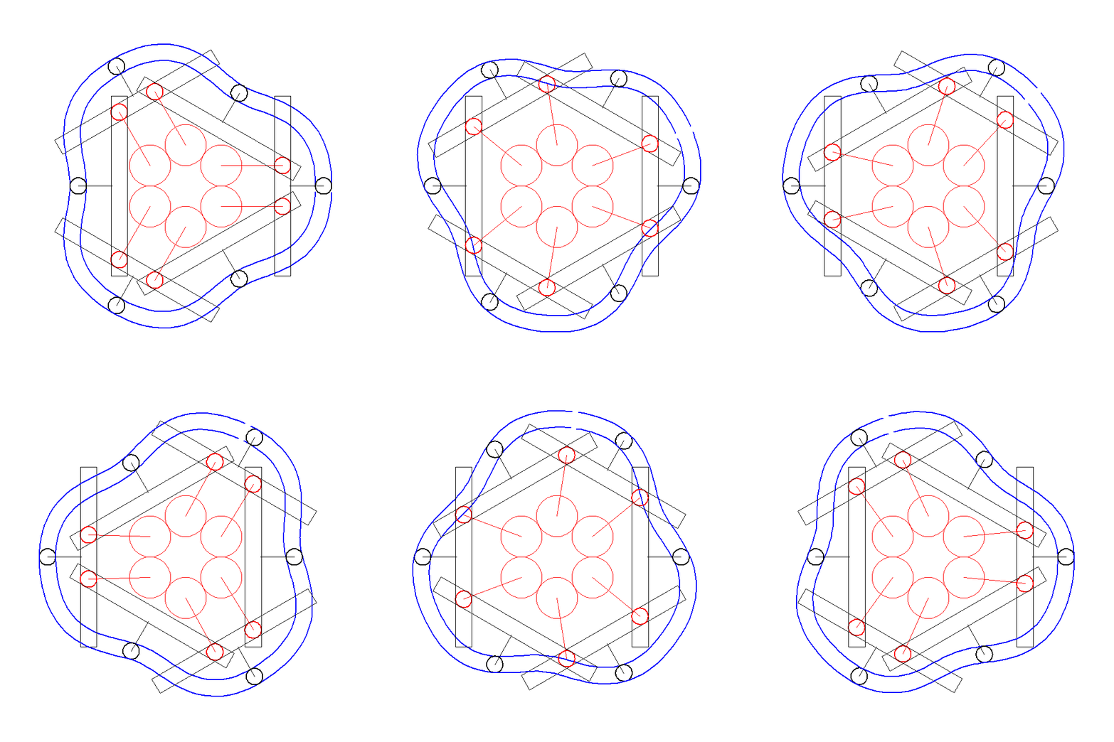
Examples of rotary central cam systems
The
following pictures show the extreme
adaptability of the rotary central cam design with all type
of PRBC engines.

p
= 2, exterior cam and pebbles

p = 2, cam and interior pebbles

p = 3, cam and exterior pebbles

p = 3, cam and interior pebbles

p = 4, cam and exterior pebbles

p = 4, cam and interior pebbles

p = 5, cam and exterior
pebbles

p = 5, cam and interior pebbles.
5.
Animations of mechanisms to rotary central cam 2Pi / cyclic p
 Piloted Motion 45°/135° and
90° of amplitude with symmetrical beating
 Piloted Motion : 0°/180° and
180° of amplitude with symmetrical beating
 Piloted Motion : 0°/90°
and 90° of amplitude with asymmetric beating
 Piloted Motion : 0°/60°
and 180° of amplitude with symmetrical beating
 Piloted Motion : 0°/36° and
36° of amplitude with asymmetric beating

Piloted Motion : 0°/60° and
60° of amplitude with super-asymmetric beating
6.
Over multi-lobed rotary central (2Pi /kp) cyclic cam
The minimal number of lobes of the rotary central cam to make the
engine run is worth the
p
number of pairs of pistons
However, the rotary central cam can be over multi-lobed, by
machining
k .
p lobes on the cam where k is positive integer superior
or equal to 2.
Why to over multi-lobe
the rotary central cam ?
it multiplies by k
the numbers necessary cycles
to 1 have one revolution of the cam...
therefore it
multiplies by k
the nominal compactness of the motor !
1.
The cam, in addition to convert the motion, plays a complementary role
of reducing gearings by a
k factor
2. The use of pebbles mounted on ball-bearings converts the power with
an output rate of about 95%
(contrary
to the successive trains of gearings whose output falls quickly unless
90% by rubbings / barbotages in oil)
3. All this functionalities are achieved by a single part with a
thickness of some millimiters
(laser
cuttable or usinable... in a simple plate of steel)
Under the condition to respect transmission angles which lead to
acceptable
efforts wether the engine works as a motor or a pump, and to give
sufficient size to the rotary central cam,
k can easily pass 3 or 4, in
particular for engines having few pairs of rotary pistons.
The following animation
belows show the extreme
variety of possible and arbitrary motions with over multi-lobed cams for
all type of PRBC engines.
 Piloted motion : 0°/180° and
180° of amplitude with asymmetric beating by a 1 x 6 over
multi-lobed cam
 Piloted motion :
0°/180° and 180° of amplitude with symmetrical
beating by an 1
x 7 over
multi-lobed cam
 Movement piloted
0°/90° and 90° of amplitude to symmetrical
beating by two (2
x 2 over
multi-lobed) cams
 Piloted motion : 0°/60° and
60° of amplitude with symmetrical beating by two (3 x 2 over multi-lobed) cams
 Piloted motion
: 0°/45° and 45° of amplitude with
asymmetric beating by a 4 x 3 over multi-lobed rotary central cam
7.
Simplifed system of conversion for 2PRBC engines
One can also develop simplified systems of conversion, especially for
2PRBC engines, it is possible to convert the motion with
only one rotary part bound on 2 manetons actuated by orthogonal
grooves, they-even manipulated by a kinematics based on a deformable
lozenge. The following system can be qualified as a double crossed
sinus mechanism.
 Piloted motion :
0°/90° and 90° of amplitude with linear
symmetrical beating

Partial view of the mechanism "doubles sinus" for a 2PRBC engine

Partial
view of front side of the mechanism "doubles sinus" for a 2PRBC
engine
in charcoal gray: orthogonal grooves,
in yellow and foreground : rotary output shaft
in yellow to the second plan : eccentric bound of the rotary pistons
blank: rod of the deformable lozenge


