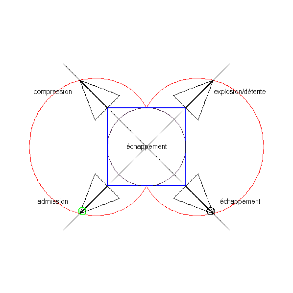
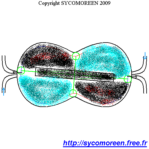
Concept
POGDC


Back to the main menu
| Concept MPRBC |
Concept
POGDC
|
Back to the main menu |
| Principles | Four times cycle | Conversion of the motion | System for variable valves' timing (VVT) | System to regulate the compression rate |

The current valves are facing 4 big problems :

Numerous kinematics have been developed :
- to transmit "globally" the displacement of the cam toward the valve (fig. III.22.)

III.22 : mechanical strategis for distribution :
a lateral camshaft and reversed valve b : camshaft in head c : lateral camshaft, pushing part, stem and tipper d : in head camshaft and tipper
- to improve the contact of the pushing with the stem of valve (fig. III.23.)

No among them doesn't distinguish itself by its compactness. Otherwise, the games, distortions and the possible vibratory resonances of the intermediate parts make difficult the precise knowledge of the law of valves' motion. For these reasons, the camshafts in head are currently the more used. Let's signal that the camshafts with tippers introduce an additionnal part : to manage the tipper. permits to adjust the amplitude of the movement of the valve insofar as one can modify the point of pivot of the tipper (fig. III.24.). Some even more complex kinematics exist as the device BMW Valvetronic (Cf. 3.c, defect n°3) with 2 tippers.

III.24. Managing of the tippers' lentgh by moving the joining point.
came: cam tringle: stem culbuteur : tipper excentirité: crankiness
One of the biggest shortcomings of the current valves is the strangling that they lead to the level of te fresh air's intake just before the room of combustion. It is inherent to their design that permits a good tightness in closed position, but entails a turbulent out-flow at the time of the admission, ominous to the good replenishment of the cylinder, especially as the motion of the piston is fast. It is one of the reasons of the recent multiplication of the number of valves in order to increase the section of passage of the fresh air because several small valves are better that only one big valve, what is worth as well for the intake that for the exhaust.
Some parades are put in place as complex shapes of pipes of admission or deflectors to permit a whirling replenishment (fig. III.25. and III.26.), but non turbulent (the lines of field of the speeds of the fluid are all tangents to a helical).

On the III.27 picture., one observes that the coefficient of air flow saturates quickly, even while opening the valve a lot. Besides, the big openings of valves sometimes oblige to achieve some necklines in the piston to avoid a piston / valve collision in beginning of admission or at the end of exhaust. One also notices that some shapes of the admission pipe encourage the coefficient of debit a lot, but such pipes are expensive to achieve in big series.

One can show experimentally that
while defining the number of Mach Z by :
D: diameter of the cylinder dS : diameter of the valve aS: celerity of the sound in air
Ump:
middle speed of the piston during the admission:  middle value of the air flow
coefficient
middle value of the air flow
coefficient
it is possible to know the rate of replenishment of the cylinder in fresh air with the help of the curve of the fig. III.28.

III.28 Replenishment rate according to Mach number Z at the intake's valve
To bette realize the resistance of the valves against the penetration of the fresh air in the room of combustion, we are going to analyze the concrete case of a 4 cylinders 2 Liter non overfed engine with 2 valves by cylinder (one for admission (intake), another for exhaust):
- cylinder of diameter 80 mm and stroke of 100 mm
- intake valve of diameter 35 mm
- speeds of rotation motor: 1000, 3500 and 7000 RPM
- speed of the sound in air: 340 m/s to 25°C
- : 0,4
Let put N the number of Rounds per Minutes (RPM), on 1 revolution of the crankshaft, the piston does a round-trip of 200 mm with our hypotheses (two strokes). It makes it in one time of 60s/N either :
- 60 ms at low RPM (slow motion) (1000 rpm), of where Ump = 3,33 m/s
- 17 ms at nominal RPM (middle motion) (3500 rpm), of where Ump = 11,76 m/s
- 8,6 ms at high RPM, (fast motion) (7000 rpm) where Ump = 23,26 m/s
What gives us : Z1000 = 0.128, Z3500 = 0.451, Z7000 = 0.893
Even at low RPM, the rate of replenishment is only from 85 to 90%. More the piston is fast and more the situation worsens (more and more strong turbulences nearly the valve): at full capacity, it is only from 65 to 75%.
Even though the increase of the number of valves and the overfeeding improve appreciably the rate of replenishment...
...the vocation of these strategies should be the optimization of the motor working
and not the correction of an inherent defect to the type of valves used.
As one saw it, the current valves must be actuated by a camshaft. For different reasons exposed in the fig. III.29., it is necessary, in the ideal, to modify the laws of valves' motions while the motor is running, according to various parameters of which most important is crankshaft's RPM. For example, in slow motion, one advances the closing of the admission valve to inhale less air and therefore less to consume. On the contrary, to high RPM, one delays it so that more of air have the time to penetrate in the room. With regard to the exhaust, one can advance the opening at high RPM to hunt to the maximum of burnt gases or on the contrary, at low RPM, delay it to have a combustion in poor mixture and less to consume. One can wish to modify the displacement of the valve also: for example, weak opening at low RPM (still for less air to inhale, therefore less fuel to consume) and strong opening to full power. Another application is running on the Miller cycle by advancing to the closing of the admission, or delaying to the closing of the admission in order to admit a volume of fresh gas lower than the maximal volume of the room.

When the constructors conceive the motors where it is possible to
achieve all these regulation for a working engine,
they establish a cartography of the advances and delays as well as of
the displacements of valves according to numerous parameters, whose 2
principals are the load of the motor (the torque to provide to the
crnakshaft) and its RPM. The fig. III.30. regroups the
main laws of valves' motions where the horizontal axis
represents the angle of rotation of the crankshaft and the vertical
axis
represents the stroke of the valve's motion.

Law 1: classical law frozen once for all : it is a compromise between the requirements of the fig. III.29. used in rustic motors (clippers, compressors.) or in the more powerful engines where the minimization of the costs is the priority goal.
Law 2: law with 2 constant delays with frozen stroke. Sometimes permitting to have an admission / exhaust recovery. If this recovery takes place, it is not adjustable.
Law 3: identical law to the law n°2, but the difference is that the delay is continuously variable. If the recovery of valve takes place, it will be adjustable. The liberty of regulating begins to really draw itself but it is still limited. Yet, very few motors can achieve this law. The designs of BMW Vanos or of the Toyota Yaris (Cf. § 3.c) apply this law of levee of valves.
Law 4: law to continously delay the opening AND or to advance the closing with constant valve stroke, feasible with the help of the Camless system (Cf. 3.c).
Laws 5 and 6: law to delay the opening (5) or to advance the closing (6), and with to variable valve's stroke as the delay to close (5) or to open (6).(feasible by Camless system)
Laws 7 and 8: law with constant valve's stroke, but to with continously delaying at the opening (7) or addvancing at the closing (8) (feasible by Camless system).
Law 9: law of both strolke and wedgings continously variable, so much to the opening that to closing, feasible by camless or by system electro-hydraulic system like FIAT designed it many years ago. Wedgings and strokes are entirely managed and continually variable (fig. III.31.).

Schema of the FIAT electro-mechanical system to manage valves: Entirely piloting of wedgings and strokes.
The 3 following points :
-
the
current valves,
solely actionable by the top of their stem, require systems of variable
wedging of an important complexity for limited results (wedgings
of about ten degrees for the crankshaft, variable displacement of about
several of the millimeters).
- The inertia of these systems is sometimes too high and the wished regulation is during several cycles the engine, corresponding to the double of crankshaft's revolutions : this is how the law n°4, a priori feasible by a Vanos, is not actually because it would be necessary that the system reacted in a very short duration in comparison to those of only one cycle.
- It is not possible to maintain constantly in position a valve while the motor is running, however it can be useful to disactivate a cylinder (valves constantly open or closed). As already seen for the Cadillac Design DoD,
The systematic use of the current valves' systems would nearly lead to forget
that other solutions are existing !
with of course more or less of success... However, it is not not useless to study themselves because some among them present advantages that the previously described valves don't have.
With regard to 2 times cycle engines, the gases exchanges make themselves in a different way of the one of the 4 times cycles since during a fraction of the stroke, the piston is used to sweep the burnt gases and simultaneously to inhale fresh air. Also, the used valves are in general very different. The simplest valves are named" "Reed valve (fig. III.32.) and went up on the cover of the 2 times cycle engines. They are constituted of 2 tabs coupled or no according to the sense of the air flow.

Sweeping in a 2 times cycle engines with a Reed valve at intake of the cover. It's opened in the sense of the air flow and closed otherwise
They present the advantage not to require any mechanical piece of order, but this simplicity poses several problems :
- limitation in frequency of the valves entailing a limited maximum RPM.
- systematic and imprecise delay of the opening at the intake disfavoring the replenishment of the cover, and therefore of the cylinder.
- systematic and imprecise delay of closing at the intake which result in the expulsion of a fraction of the fresh gases out of the cover.
- impossible use to the periphery of the combustion rooms because : on the one hand, their tightness is insufficient, on the other hand, they don't support aggressive conditions of temperature and pressure.
The 2 times cycle engines frequently use a sheath including various lights of admission and exhaust (fig. III.32.). These lights are sliding along the cover or the stationary lights of the cylinder, what permits their opening and their closing periodically. The motion of the sheath is assured by a supplementary rod whose crank is in hold with the crankshaft, either via a gearing, either via a strap. The main advantage of this system is the speed of closings and openings of lights, what is encouraging a strong rate of replenishment. The drawbacks are :
- An almost impossible regulation of the wedging and the sections for valves'opening while the engine is running.
- An important mechanical power given by on the crankshaft to actuate the sheath.
- A little efficient tightness of the sheath.
If we are now interested in the 4 times cycle engines, systems of rotary valves already exist, but are not really very spread. Practically no motorist industrializes these types of valves that generally remain to the step of prototype (fig. IV.15.).

IV.15 Rotary valves a: perpendicular axis to the cylinder's axis b: coaxial axes with the cylinder's axis (ASPIN Design)
Two alternatives have been considered: perpendicular of the valve's axis of rotation to the axis of the cylinder (a), or parallel (b).
The 2 solutions present the same advantages and inconveniences :
· Advantages
o big sections of passage of gases, pledge of a replenishment and an ejection of the very efficient burnt gases.
o variable wedging of the valves' rotation angle by report the one of the crankshaft with systems similar to the BMW Vanos or to the VVT of the Toyota
o very peed of opening and closing.
o precision of the instants of opening or closing because the mechanical games or the distortions of the parts have little influence on the lights' angle of rotation through which flows out the gases.
· Shortcomings
o Necessity to use a conical gearing to transmit the motion from the cranshaft to the valves because their axes are orthogonal (a simple strap is not sufficient).
o Weak tightness of the valves, the least game or a light on the circular peripheries of the valves quickly damage the tightness.
Even though one can consider the implantation on new SYCOMOREEN engines of most systems of valves previously described, we are going to draw up the list of the features of the ideal system of valves :
1. to have a flattest as possible system in order not to increase too much the motor's thickness.
2. think about a mechanical connection with the output shaft the most compact as possible: a simple strap or a gearing must be sufficient.
3. to need only a weak mechanical power to actuate the valves.
It requires the following conditions :
1. sufficient tightness of the valves in closed position
2. high peed of valves' closings and openings
3. big section of passage for fresh gases
4. reduction of the losses in the intake duct :
o to reduce the number of direction changes for the fluid
o to encourage a non turbulent air flow : no obstacle on the main flow air..
5. possible increase of the number of valves by room
Let's recall the fifth function of the specifications overview :
| Function | Criterias | Level | Flexibility | Commentary |
| 5: To permit a big liberty of variable wedging of the valves | Amplitude of regulation for the wedging angle of the valve | + / - 360° | At least | The variable wedging permits indispensable adjustments to respect the anti-polluting norms and to grant the power of the motor. It also allows to achieve the Miller cycle by an advance of the admission closing (reduced consumption) |
| Speed of regulation of the wedging | 1 / 10 of the time necessary to 1 motor cycle in the concerned room | At more | The variable wedging must be fast in comparison to duration of one motor cycle. | |
| Independence of a room to the other | Total independence of a room to the other | / | It is necessary to be able to adjust independently each room to activate / disactivate the combustion at will | |
| Possibility to maintain a valve constantly in the same position while the motor is running | Open, closed or partially opened | All possible position | In order to continuously plug / open the valves , what can have some applications to extinguish some comustion rooms and even to convert them into compressor in the aim of a compressed air storage for braking phases |
None of the valves' systems of the § 5.a and § 5.b doesn't respect the conditions required by these 4 features simultaneously.
before to go further, we notice that the rotary POGDC don't need for valves anymore because they are running with continuous intake and exhaust.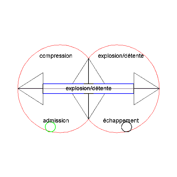
The rotary POGDC with turning carter doesn't need for valves !
The rotary POGDC with fixed carter doesn't need for valves !
The rotary "double burning" POGDC with fixed carter doesn't need for valves !
but only a simple blowing device of fresh air !
The invention is about a device
designed to
open and close periodically some pipes where gaseous, liquid or
polyphasic fluids are flowing. The invention is an anti-friction
epicyclic rotary valve (in French : Soupape Anti-Erosion
à
Rotations Epicycloïdales SAERE). The SAERE system is fullfilling
all the specifications of the array below and is characterized by:
1. a rotary obturator directly controlled
by the rotary motions of epicyclic gearings,
2. the obturator is rotating between 2 stops with
ball-bearings,
3. only one
shaft of the epicyclic gearings allows to regulate continuously and at will both the times of
opening/closing of the pipe and the area offered to the fluid which is
flowing through it,
4. some sculptures at the periphery of
the rotary disc.
")
")
 fully controlled in phase and in lift, with 8 SAERE for a conventional 4-cylinders motor")
As
showed on the views below and above, a central alley can be arranged
for the implantation of
spark-plugs or injectors exactly in the center of every cylinder .

On the following schema are illustrated the SAERE
systems which optimize to the maximum the flowing areas. We can see
there that the
maximum area of the out-flow can raise to 1/3 of the surface of one
cylinder for the intake, and another 1/3 for the exhaust (the remaining
1/3 will preferably be allowed to the mounting of spark-plugs,
injectors or pre-heating devices).
SAERE has also the advantage not to deviate the fluid's
trajectory, which is naturally attracted axially along the cylinder
(whereas a conventional valve which deviates the out-flow at
90° and offers a very limited flowing surface) :

Below, one under-sight of a typical 8 SAERE's arrangement for a 4-cylinders engine :
Variable Valve Timing(VVT) fully
controllable in phase and in lift independently for each room of
combustion,
what is fulfilling the
specifications required for SYCOMOREEN's valves.

Nevertheless, the
present invention will find its use especially in the devices MPRBC and POGDC(not
rotary). The SAERE device is an improvement of the system for
variable valve timing both in phase and lift already used and very
partially described in the patents "Machine
à Pistons Rotatifs à Battement
Contrôlé(MPRBC) du 19/12/2007" and "Piston
Octogonal à Géométrie
Déformable Contrôlée (POGDC)"du
19/02/2009.
For example, the systems of gaseous exchanges (SAERE) can be mounted at the same places as the green valves with pink rotor, on the following views :


We
will find a detailed state of the art concerning the technologies of
valves (basic mechanisms and "Variable Valve
Timing") in the SAERE
patent and here
is the synthesis from it in 4 points :
Point
n°1:
The rotary valves haven't completely defeated their problems of
friction or
tightness linked with their erosion. Nonetheless, they keep to be
interesting as their rotary uniform motion allows a big flowing area
for the fluid and quick opening/closing of the valve.
Point
n°2
: The poppet valves are leading regardless of complex kinematics to
actuate them. The flowing area is also very small.
Point
n°3:
The "Variable Valve Timing" (VVT) systems miss to regulate the phase
AND the lift with only one actuator(CMD) ; moreover, the range of
regulation are often limited to about ten degrees for the phase and
some millimeters for the lift,
sometimes with shocks between mobile parts.
Point
n°4 : Very few VVT mechanisms use epicyclic
gearings with 2 entries : one main entry(PRI) while the another one is
regulating(REG).
The invention is distinctly different of the state of the present art, as well by its mechanical structure that by its technical advantages.
 : Scraped and annoted view") It is composed by (see
above and below) :
It is composed by (see
above and below) :
* one pedestal(SOC) having an annular protuberance(PAN) inside which
takes place the first stop with ball-bearing(BAB1) and on which are
arranged some grooves for a circular sealing (SEGA,SEGB)
allowing the tightness. The pedestal(SOC) has at least one circulating
passage(LUM)
around of which horizontal sealings (SEGC,SEGD) can distribute
themselves,
* one rotary disc as an obturator(OBT) with
peripheral sculptures(SCU,SCU1,SCU2…) to open and close
without
shock choc the circulating passage(LUM) pierced through the
pedestal(SOC) and connected with a room(CHA). Some peripheral grooves
are arranged for another sealings(SEGE, SEGF,SEGG) to get tightness,
* one cover(CAR) which is over the rotary disc(OBT) and pushing on it
through the second stop with ball-bearing(BAB2) and one screwed or
welded assembly on the pedestal(SOC), with an exchange passage(ECH),
* one epicyclic gearing at the top,
composed by a planetary(PLA), satellites
(SAT,SAT1,SAT2…) and a satellites' carrier(PST) and one
crown(COU) : among (COU,PLA,PST), one is bound to the rotary
obturator (OBT), the other is the main rotary entry(PRI)
coming
from the
machine(MAC), and the last one is the only regulating entry (REG) via
(CMD),
* any device to command(CMD) , able to impose for the regulating
entry(REG) a controlled rotary motion : electric motor, gearing,,
worm-gearing, straps, chain...
* one optional lubrication.
 : annoted and in cut view")
The reached technical
performances are :
- valve with appreciably uniform rotary
motion, big
flowing areas and quick opening/closing without shock between the parts,
- valve with very reduced friction,
thanks to the 2
stops with ball-bearing and to the numerous
rollings(RLT1,RLT2…)
which grant very few dissipative internal rotary motions, even without
lubrication,
- valve with variable management fully
controllable
in phase and in lift with only one rotary actuator to choose
among(COU,PST,PLA), and controlled by the commanding device(CMD).
Thus, the drawbacks of points
n°1 and 2 are
cancelled while the advantages are remaining. The VVT system, whereas
the point n°3, needs only one rotary shaft angulary controlled
by
the commanding organ(CMD) : this command can use 2 ways :
- the static way (fixed shaft): it
controls the phase with the angular position,
- the dynamic way (rotary shaft): it regulates
the lift,
thus the flowing areas for the fluid with the angular velocity ; it can
even keep constantly opened/closed the circulating passage (LUM) while
blocking the position of the rotary obturator(OBT).
 : annoted and exploded views")
As the epicyclic gearing is a bi-mobile mechanism, the positions of his parts require to know 3 rotary motions : the rotation of the planetary(PLA), the one of the satellites' carrier(PST) and the one of the crown(COU). That is why an epicyclic gearing achieves an optimum in the set of a variable valve timing: as showed below, there is 6 combinations to allocate the roles "main rotation(PRI)", "regulating rotation(REG)" and "rotation of the obturator(OBT)" to the kinematic elements(PLA,PST,COU) of an epicyclic gearing. The main rotation(PRI) comes from the machine(MAC) and the regulating rotation (REG) comes from the commanding organ(CMD).

The animations below illustrate the very wide abilities of
variable valve timing fully controllable in phase and in lift of
the SAERE system. :

 can quickly block the SAERE 's obturator at any time and in any position.")
")


| Principles | Four times cycle | Conversion of the motion | System for variable valves' timing (VVT) | System to regulate the compression rate |
| Concept MPRBC |
Concept
POGDC
|
Back to the main menu |